MIDIator mix methods

The first instances of the MIDIator could sum two analysis signals, with separate scaling and sign inversion for each one. Recently, we’ve added two new methods for mixing those two signals, so it warrants this post to explain how it works and which problems it is intended to solve.

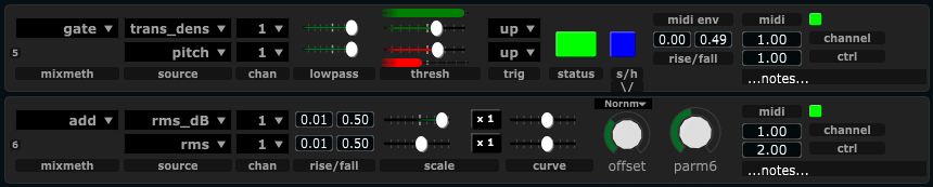
For all mix methods there is a MIDI output configuration to the right. All modules output MIDI controller values. We can set the MIDI channel and controller number, enable/disable the module, and also enter notes about the mapping/use of the module. Notes will be saved with the project.

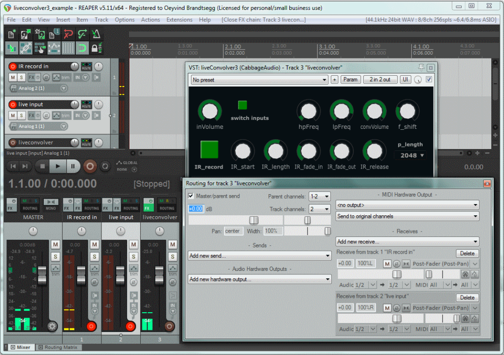
Do take care however, for your own records, take a screenshot of your settings and save this with your project. The plugins can and will change during the further development of the project. If this leads to changes in the GUI configuration (i.e. the number of user interface elements) changes, there is a high probability that not everything will be recalled correctly. In that case you must reconstruct your settings from the (previously saved) screenshot.

Add

Each of the two signals have separate filtering, with separate setting for the rise and fall times. The two signals are scaled (with scale range being from -1 to + 1), and then added together. If both signals are scaled positively, each of them affects the output positively. If one is scaled negatively and the other positively, more complex interactions between them will form. For example, with rms (amplitude) being scaled negatively while transient density is scaled positively; the output will increase with high transient density, but only if we are not playing loud.

midiator_add
Example of the “add” mix method. Higher amplitude (rms) will decrease the output, while higher transient density will increase the output. This means that soft fast playing will produce the highest possible output with these settings.

Abs_diff

This somewhat cryptic term refers to the absolute difference between two signals. We can use it to create an interaction model between two signals, where the output goes high only if the two analysis signals are very diffferent . For example, if we analyze amplitude (rms) from two different musicians, the resulting signal will be low as long as they both play in the same dynamic register. If one plays loud while the other plays soft, the output will be high, regardless of which of the two plays loud. It could also of course be applied to two different analysis signals from the same musician, for example the difference between pitch and the spectral centroid.

midiator_absdiff
Example of the abd_diff mix method. Here we take the difference in amplitude between two different acoustic sources. The higher the difference, the higher the output, regardless of which of the two inputs are loudest.

Gate

The gate mixmethod can be used to turn things on or off. It can also be used to enable/disable the processing of another MIDIator module, effectively acting as a sample and hold gate. The two input channels now are used for different purposes: one channel turns the gate on , the other channel turns the trigger off . Each channel has a separate activation threshold (and selection if the signal must pass the threshold moving upwards or downwards to activate). For simple purposes, this can act like a Schmitt trigger , also termed hysteresis in some applications. This can be used to reduce jitter noise in the output, since the activation and deactivation thresholds can be different.

midiator_gate_same
Gate mixmethod used to create a Schmitt trigger. The input signal must go higher than the activation threshold to turn on. Then it will stay on until the input signal crosses the lower deactivation threshold.

It can also be used to create more untraditional gates. A simple variation let us create a gate that is activated only if the input signal is within a specified band. To do this, the activation threshold must be lower than the deactivation threshold, like this:

midiator_gate_same_band
Band-activated gate. The gate will be activated once the signal crosses the (low) activation threshold. Then it will be turned off once the signal crosses the (higher) deactivation threshold in an upward direction. To activate again, the signal must go lower than the activation threshold.

The up/down triggers can be adjusted to fine tune how the gate responds to the input signal. For example, looking at the band-activated gate above: If we change the deactivation trigger to “down”, then the gate will only turn off after the signal has been higher than the deactivation threshold and then is moving downwards .

So far, we’ve only looked at examples where the two input signals to the gate is the same signal. Since the two input signals can be diffeerent (even come from two different acoustic source, highly intricate gate behaviour can be constructed. Even though the conception of such signal-interdependent gates can be complex (inventing which signals could interact in a meaningful way), the actual operation of the gate is technically no different. Just for the case of the example, here’s a gate that will turn on if the transient density goes high, then it will turn off when the pitch goes high. To activate the gate again, the transient density must first go low , then high .

midiator_gate_different
Gate with different activation and deactivation signals. Transient density will activate the gate, while pitch will deactivate it.

Sample and hold:

The gate mixmethod also can affect the operation of another MIDIator module. is currently hardcoded, so that it will only affect the next module (the one right below the gate). This means that, when the gate is on, the next MIDIator module will work as normal, but when the gate is turned off it will retain the value it has reached at the moment the gate is turned off. In traditional signal processing terms: sample and hold . To enable this function, turn on the button labeled “s/h”.

midiator_gate_sh
The topmost of these two modules agt as a sample and hold gate for the lower module. The lower module mapping amplitude to positively affect the output value, but is only enabled when the topmost gate is activated. The situation in the figure shows the gate enabled.

Audio effect: Liveconvolver3

The convolution audio effect is traditionally used to sample a room to create artificial reverb. Others have used it extensively for creative purposes, for example convolving guitars with angle grinders and trains. The technology normally requires recording a sound, then analyzing it and then finally loading the analyzed impulse response (IR) into an effect to use it. The Liveconvolver3 let you live sample the impulse response and start convolving even before the recording is finished.

In the context of the crossadaptive project, convolution can be a nice way of imprinting the characteristics of one audio source on another. The live sampling of the IR is necessary to facilitate using it in an improvised manner, reacting immediately to what is played here and now.

There are some aesthetic challenges , namely how to avoid everything turning into a (somewhat beautiful) mush. This is because in convolution all samples of one sound is multiplied with every sample of the other sound. If we sample a long melodic line as the IR, a mere click of the toungue on the other audio channel will fire the whole melodic segment once. Several clicks will create separate echoes of the melody, and a coninuous sound will create literally thousands of echoes. What is nice is that only frequencies that the two signals have in common will come out of the process. So a light whisper will create a high frequency whispering melody (with the long IR described above), while a deep and resonant drone will just let those (spectral) parts of the IR through. Since the IR contains a recording not only of spectral content but also of its evolution over  time, it can lend spectrotemporal morphing features from one sound to another. To reduce the mushyness of the processed sound, we can enhance the transients and reduce the sustained parts of the input sound. Even though this kind of (exaggerated) transient designer processing might sound artificial on its own, it can work well in the context of convolutions. The current implementation, Liveconvolver3, does not include this kind of transient processing, but we have done this earlier so it will be easy to add.

There are also some technical challenges to using this technique in a live setting. These are related to amplitude control, and to the risk of feedback when playing on larger speaker systems. The feedback risk occurs because we are taking a spectral snapshop (the impulse response) of the room we are currently playing in (well, of an instrument in that room, but nevertheless, the room is there), then we process sound coming from (another source in) the same room. The output of the process will enhance those frequencies that the two sources have in common, hence the characteristics of the room (and the speaker system) will be amplified, and this generally creates the risk of feedback to arise. Once we have unwanted feedback with convolution, it will also generally take a while (a few seconds) to get rid of, since the nature of the process creates a revereb-like tail to every sound. To reduce the risk of feedback we use a very small frequency shift of the convolver output. This is not usually perceptible, but it disturbs the feedback chain sufficiently to significantly reduce the feedback potential.

The challenge of the overall amplitude control can be tackled by using the sum of all amplitudes in the IR as a normalization factor. This works reasonably well, and is how we do it in the liveconvolver. One obvious exeption being in the case where the IR and the input sound contains overlapping strong resonances (or single lone notes). Then we will get a lot of energy on those overlapping frequency regions, and very little else. We will work on algorithms to attempt normalization in these cases as well.

The effect

liveconvolver3_reaper_setup
Liveconvolver3 in an example setup in Reaper. Note the routing of the source signals to the two inputs of the effect (aux sends with pan).

The effect uses two separate audio inputs, one for the impulse response sampling, and one for the live input to be convolved.  We have made it as a stereo effect, but do not expect it to convolve a stereo input. It also creates a mono output in the current implementation (the same signal on both stereo outputs). In the figure we see two input sources. Track 1 receives external audio, and routes it to an aux send to the liveconvolver track, panned left so that it will enter only input 1 to the effect.. Track 2 receives external audio and similarly routes it to an aux send to the liveconvolver track, but panned right so the audio is only sent to input 2 of the effect.

The effect itself has contols for input level, highpass filtering ( hpFreq ), lowpass frequency ( lpFreq ) and output volume ( convVolume ). These controls basically do what the control name says. Then we have controls to set the start time ( IR_start ) of the impulse response (allow skipping a certain number of seconds into the recording), and the impulse response length ( IR_length ), determining how many seconds of the IR recording we want to use. There are also controls for fading the IR in and out. Without fading, we might experience clicks and pops in the output. The partition length sets the size of partitioned convolution, higher settings will require less CPU but will also make it respond slower. Usually just leave this at the default 2048. The big green button IR_record enables recording of an impulse response. The current max duration is 5.9 seconds at 44.1 kHz sampling rate. If the maximum duration is exceeded during recording, the recording simply stops and is treated as complete. The convolution process will keep running while recording, using parts of the newly recorded IR as they become available. The IR_release knob controls the amount of overlap between the new instances of convolution created during recording. When recording is done, we fall back to using just one instance again. Finally, the switch_inputs button let us (surprise!) switch the two inputs, so that input 1 will be the IR record and input 2 will be the convolver input. If you want to convolve a source with itself, you would first record an IR then switch the inputs so that the same source would be convolved with its own (previously recorded) IR. Finally, to reduce the potential of audio feedback, the f_shift control can be adjusted. This shifts the entire output upwards by the amount selected. Usually around 1 Hz is sufficient. Extreme settings will create artificial sounding effects and cascading delays.

Installation

The effect is written in the audio programming language Csound , and compiled into a VST plugin using a tool called Cabbage . The actual program code is just a small text file (a csd) that you can download here .

You will need to download Cabbage (the bleeding edge version can be found here ), then open the csd file in Cabbage and export it as a plugin effect. Put the exported plugin somewhere in your VST path so that your favourite DAW can find it. Then you’re all set.

cabbage_export_liveconvolver
Export as plugin effect in Cabbage

Routing in other hosts

As a short update, I just came to think that some users might find it complicated to translate that Reaper routing setup to other hosts. I know a lot of people are using Ableton Live, so here’s a screenshot of how to route for the liveconvolver in Live:

liveconvolver3_live_setup
Example setup with the liveconvolver in Live

Note that

  • the aux sends are “post” (otherwise the sound would not go through the pan pot, and we need that).
  • Because the sends are post, the volume fader has to be up. We will probably not want to hear the direct unprocessed sound, so the “Audio To” selector on the channels is set to “Sends only”
  • Both input channels send to the same effect
  • The two input channel are panned hard left (ch 1) and hard right (ch 2)
  • The monitor selector for the channels is set to “in”, activating the input regardless of arm/recording

Whith all that set up, you can hit “IR_record” and record an IR (of the sound you have on channel 1). The convolver effect will be applied to the sound on channel 2.